|
| ||||||||||||||||||||
|
| ||||||||||||||||||||
COMPOSITE RESEARCH: Composite bridge plugs used in
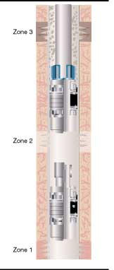
multi-zone wells to avoid costly kill-weight fluids The composite bridge plug (CBP) was developed primarily to give the operator the option of setting several cased hole bridge plugs in a single wellbore to isolate multiple zones, and quickly remove them from the wellbore using conventional milling tools after the remedial operation has been completed. This technology enables the operator to independently treat and test several zones, selectively isolate each zone, and then remove multiple bridge plugs in an under-balanced environment. Typically, the under-balanced removal of composite bridge plugs is accomplished with coiled-tubing-deployed downhole motors and milling tools. An operator's main objectives in completing a multi-zone, co-mingled gas well are to independently perforate, treat, and isolate each zone of interest without damaging the formation, and to leave a clean wellbore that will produce the zones when the treatment of each zone is complete. Cast iron bridge plugs (CBP) and retrievable-type bridge plugs have been used in the past to isolate multiple zones in a wellbore for selective treatments. CBPs require heavyweight fluids to remove cuttings from the wellbore. These heavyweight fluids have the potential to damage lower pressure zones. In a well with multiple zones, using multiple cast iron plugs in a single wellbore can make removal of the plugs very difficult due to the heavy weight of the cast iron cuttings under the mill and the difficulty in circulating the cast iron cuttings from the wellbore. When using multiple retrievable-type bridge plugs, the operation of setting and retrieving the plugs can amount to twice as many runs in the hole as with CBPs. Even considering the speed of wireline methods for retrievable bridge plugs, removing multiple CBPs by coiled tubing is still more cost effective. For example, a well contains distinct zones of interest with varying bottomhole pressures where each zone needs to be perforated, treated, and isolated. The varying bottomhole pressures can make remedial operations difficult, especially when a zone of higher bottomhole pressure equivalent is below a target zone. Any attempt to use kill-weight fluids or frac fluids in one zone could result in formation damage to other zones after perforating. Zone isolation
To begin a remedial operation, the lower zone would be perforated, treated, and isolated with a CBP. This can be run on conventional wireline setting tools or coiled-tubing-conveyed setting tools. Both wireline and coiled tubing setting tools can be run in the well under pressure, so there is no need for kill-weight fluids to be used. After the first CBP is in place, the lower zone is isolated from the other zones in the well. This protects the zone from further treatments on the remaining zones. After the first CBP is set, the middle zone can be perforated and treated. The characteristics of the CBP allow treating pressures above the plug up to 10,000 psi during normal treating operations. The first CBP protects the lower zone when higher operating pressures are necessary on the middle zone. The middle zone then can be isolated and protected by another CBP, and the upper zone can then be perforated and treated without compromising the integrity of the middle and lower zones. This technique of discrete treatment and isolation may be repeated until all zones have been treated. The plugs allow discrete treatment of multiple zones having bottomhole pressure equivalents, while minimizing formation damage that can occur with the use of heavyweight fluids. Removal procedureAfter treating the three zones of interest in the wellbore, the operator's next objective is to put the well on production. The CBP can be removed under pressure in the absence of kill-weight fluids and are ideal tools to be removed in an under-balanced environment utilizing coiled-tubing-conveyed mills and motors. A collection of removal technologies consists of:
The combination of these three technologies will fit well in the under-balanced environment. Thru-tubing fishing equipment allows the CBP to be drilled without rotating the pipe, and accessory equipment exists to allow many different functions to take place during and after the milling. Since snubbing units and kill weight fluids are not needed, coiled tubing is a very effective deployment method. Coiled-tubing-conveyed downhole mills and motors are deployed as a bottomhole assembly, providing maximum drill-out efficiency. The material used for the CBP was designed and tested for maximum cuttings removal when milled by coiled tubing mills and motors. Safety featuresSeveral safety features enable the CBP to perform to operator specifications: (1) The design allows it to hold a substantial differential pressure for 10 days without a cement cap on top of the plug. This eliminates the inconvenience of dumping cement on top of the plug when cement is not readily available in the area. A potential danger associated with dumping cement on top of a CBP is that time and exposure can cause a phenomenon referred to as the 'roll effect.' This effect is more susceptible to button-type slip technology than the full-circle type slip designs. Essentially, the well environment will break down the bond between the slip body and the buttons. The breakdown in the bond causes the bridge plug to lose pressure containment by allowing the buttons to roll out of the slip. As the cement cap is removed, there is no longer a slip engagement in the casing to keep the pressure from blowing downhole equipment out of the hole. This type of blowout is especially dangerous when using coiled tubing due to the lack of weight available. Full-circle type slip technology combats the roll effect by using a cast-iron slip insert imbedded in the composite slip body, with an extensive area of contact that will hold the slips together in well environments. Effectively, the cast-iron slip inserts used in the full-circle type slip design are not prone to roll effect. (2) Another safety feature that allows safe drill-out is the ability to 'top vent' during removal. As the mill is removing the top portion, the plugging device inside will be removed before the top set of slips. This will allow pressure to equalize above and below the plug before the top set of slips are removed. The plug will remain anchored in the casing by the slips while the plug equalizes. These plugs can succumb to a phenomenon known as the 'floating mandrel.' After setting, the outer components of the plug (slips, cones, back-up rings, etc.) are independent from the mandrel. Since the anchoring device is located in the outer components, the mandrel is free to move. Pressure reversals can cause the mandrel to move up and down, or float in relation to the outer components. These movements of the mandrel can break down the seal between the outer components and the mandrel, creating a leak path. A 'floating mandrel' can ultimately lead to a pressure integrity breakdown. The addition of a body-lock ring will counteract these effects. The body-lock ring effectively locks the outer components of the plug to the mandrel. Therefore, the anchoring of the slips is transmitted to the mandrel keeping it in place during pressure reversals. Utilization of a body-lock ring will have a longer life as related to pressure containment. Removal efficiencyThe composite material used has been designed and tested for maximum cuttings removal efficiency in milling environments that are characterized by low viscosity milling fluids and low annular velocities. This type of environment produces very poor sweep efficiencies as related to cuttings removal. Low viscosity fluids are typically used to limit formation damage to low-pressure zones. Low annular velocities are created due to the increased annular area between the casing ID and the coiled tubing OD, and the relatively low pump rates that are typical of coiled tubing operations. Removing with low viscosity drilling fluids greatly reduces the potential for formation damage. During the removal process, composite cuttings are easily circulated back to surface. However, when removing multiple CBPs from the wellbore, a portion of the top plug may fall on the top of the next plug as the milling operation progresses. A clutching mechanism on the top and bottom of each plug will lock components from multiple plugs together and prevent them from rotating in the wellbore as the milling continues. A plug design with a clutching mechanism on only one side will have a tendency to spin on the top of the next plug as the plugs are being removed. Milling operationsAn interlocking back-up ring system will support the packing elements, for increasing pressure integrity, and also keep the back-up rings from spinning during milling operations. As milling continues through the composite bridge plug, a back-up ring system that does not interlock has a tendency to spin along with the rotation of the mill. This makes milling through the plug extremely difficult, especially if the backup rings are composed of a metallic material, such as brass. Reduced mill-out times have been attributed to a combination of the interlocking pedal design of the back-up rings and the composite material construction used for the back-up rings. The non-metallic back-up rings also facilitate the use of full gauge mills. Metallic backup rings on composite bridge plugs require an under-gauge mill, and under-gauge milling can leave large pieces of debris in the wellbore. Composite bridge plugs that use button-type slip technology for casing engagement can be difficult to remove from the wellbore. The buttons used in the slips are constructed mainly of tungsten carbide - a very dense and very hard material. These tungsten carbide buttons cannot be easily circulated out of the hole because of their high density and cannot be milled because of their excessive hardness. Therefore, the tungsten carbide buttons will begin to collect under the mill and on top of the composite bridge plug. The collection of the buttons will act like ball bearings under the mill's cutting surface and make milling progression extremely slow. Also, tungsten carbide buttons can scar downhole equipment and casing walls. Case historiesDatabase history of the newest plug has recorded more than 250 runs. The jobs have recorded a wide variety of downhole conditions including the following:
In most cases, the CBP has been deployed on wireline, but runs on coiled tubing are not uncommon. Drill-up times have averaged 20-25 minutes per plug, with the shortest time recorded at 10 minutes. The newest plug designs have been run in fields in Texas, Oklahoma, Wyoming, and Louisiana. International areas include the North Sea, Holland, Mexico, and Saudi Arabia. The casing sizes developed so far include 2-7/8 in., 3-1/2 in., 4-1/2 in. and 5-1/2 in., and other casing and tubing sizes are being developed. Most of the drill-ups have been accomplished with coiled tubing in an under-balanced condition. The plug provides an effective zone isolation device and can be quickly removed from the wellbore. Zones of interest can be perforated and treated with minimal formation damage, and the removal characteristics of the composite material allow it to be circulated out of the hole with low viscosity fluids and low annular velocities associated with coiled tubing. Editor's Note: This is an updated summary of the SPE 67200 paper, presented at the SPE Production and Operations Symposium held in Oklahoma City, Oklahoma, on 24-27 March 2001. | |||||||||||||||||||||||||||||||||||||
|
| |||||||||||
| ||||||||||||